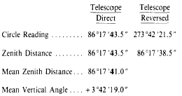
|
ENGINEER’S TRANSIT
A primary survey fieldwork consists of measuring horizontal
and vertical angles or directions and extending straight lines. The instruments that can perform these functions have additional
refinements (built-in) that can be used for other survey operations, such as leveling. Two types of instruments that fall
into this category are the engineer’s transit and the theodolite. In recent years, manufacturing improvements have permitted
construction of direct-reading theodolites that are soon to replace the vernier-reading transits. However, in most SEABEE
construction, the engineer’s transit is still the major surveying instrument.
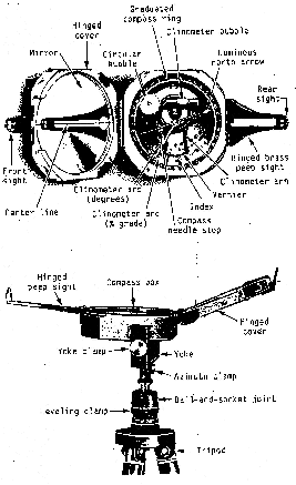
Figure 11-5.-A Brunton pocket transit.
The transit (fig. 11-6) is often called the universal survey
instrument because of its uses. It may be used for measuring horizontal angles and directions, vertical angles, and differences
in elevations; for prolonging straight lines; and for measuring distances by stadia. Although transits of various manufacturers
differ in appearance, they are alike in their essential parts and operations.
The engineer’s transit contains several hundred parts. For-descriptive purposes, these parts may be grouped into three assemblies: the leveling
head assembly, the lower plate assembly, and the upper many plate or alidade
assembly (fig. 11-7).
Leveling Head Assembly
The leveling head of the transit normally is the four-screw
type, constructed so the instrument can be shifted on the foot plate for centering
over a marked point on the ground.
Lower Plate Assembly
The lower plate assembly of the transit consists of a hollow spindle that is perpendicular to the
Figure 11-6.-An engineer’s transit.
Figure 11-7.-An engineer’s transit, exploded view.
center of a circular plate and accurately fitted the socket in
the leveling head. The lower plate contains the graduated horizontal circle on which the values of horizontal angles are read
with the aid of two verniers, A and B, set on the opposite sides of the circle. A clamp controls the rotation of the lower
plate and provides a means for locking it in place. A slow-motion tangent screw is used to rotate the lower plate a small
amount to relative to the leveling head. The rotation accomplished by the use of the lower clamp and tangent screw is known
as the LOWER MOTION
UppePlate
or Alidade Assemblyr
The upper plate, alidade, or vernier assembly consists of a spindle
attached plate to a circular plate carrying verniers, telescope standards, plate-level vials, and a magnetic compass. The
spindle is accurately fitted to coincide with the socket in the lower plate spindle.
A clamp is tightened to hold the two plates
together or loosened to permit the upper plate to rotate relative to the lower plate. A tangent screw permits the upper plate
to be moved a small amount and is known as the UPPER MOTION.
The standards support two pivots with adjustable
bearings that hold the horizontal axis and permit the telescope to move on a vertical plane. The vertical circle moves with
the telescope. A clamp and tangent screw are provided to control this vertical movement. The vernier for the vertical circle
is attached to the left standard. The telescope is an erecting type and magnifies the image about 18 to 25 times. The reticle
contains stadia hairs in addition to the cross hairs. A magnetic compass is mounted on the upper plate between the two standards
and consists of a magnetized needle pivoted on a jeweled bearing at the center of a graduated circle. A means is provided
for lifting the needle off the pivot to protect the bearing when the compass is not in use.
LEVEL VIALS.— Two plate level vials (fig. 11-6) are placed at right angles to each other. On many transits, one plate level vial
is mounted on the left side, attached to the standard, under the
Figure 11-8.-Horizontal scales, 20 second transit.
vertical circle vernier. The other vial is then
parallel to the axis of rotation for the vertical motion. The sensitivity of the plate level vial bubbles is about 70 sec
of movement for 2 mm of tilt. Most engineer’s transits have a level vial mounted on the telescope to level it. The sensitivity
of this bubble is about 30 sec per 2-mm t i l t.
CIRCLES
AND VERNIERS.— The hori-zontal and vertical circles and their verniers are the parts of the engineer’s
transit by which the values of horizontal and vertical angles are determined. A stadia arc is also included with the vertical circle on some transits.
The horizontal circle and verniers of the transit
that are issued to SEABEE units are graduated to give least readings of either 1 min or 20 sec of arc. The horizontal circle
is mounted on the lower plate. It is graduated to 15 min for the 20-sec transit (fig. 11-8) and 30 min for the 1-min transit
(fig. 11-9). The plates are numbered from 0° to 360°, starting with a common point and running both ways around the circle.
Two double verniers, known as the A and B verniers, are mounted on the upper plate with their indexes at circle readings 180°
apart. A double vernier is one that can be read in both directions from the index line. The verniers reduce the circle graduations
to the final reading of either 20 sec or 1 min.
Figure 11-9.-Horizontal scales, 1-minute transit.
The A vernier is used when the telescope is in its
normal position, and the B vernier is used when the telescope is plunged.
The VERTICAL CIRCLE of the transit (fig. 11-10)
is fixed to the horizontal axis so it will rotate with the telescope. The vertical circle normally is graduated to 30´ with
10° numbering. Each quadrant is numbered from 0° to 90°; the 00 graduations define a horizontal plane, and the 90° graduations
lie in the vertical plane of the instrument. The double vernier used with the circle is attached to the left standard of the
transit, and its least reading is 1´. The left half of the double vernier is used for reading angles of depression, and the
right half of this vernier is used for reading angles of elevation. Care must be taken to read the vernier in the direction
that applies to the angle observed.
In addition to the vernier, the vertical circle may
have an H and V (or HOR and VERT) series of graduations, called the STADIA ARC (fig. 11-10). The H scale is adjusted to read
100 when the line of sight is level, and the graduations decrease in both directions from the level line. The other scale,
V, is graduated with 50 at level, to 10 as the telescope is depressed, and to 90 as it is elevated.
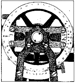
Figure 11-10.-Vertical circle with verniers,
scales, and stadia arc.
The VERNIER, or vernier scale, is an auxiliary
device by which a uniformly graduated main scale can be accurately read to a fractional part of a division. Both scales may
be straight as on a leveling rod or curved as on the circles of a transit. The vernier is uniformly divided, but each division
is either slightly smaller (direct vernier) or slightly larger (retrograde vernier) than a division of the main scale (fig.
11-11). The amount a vernier division differs from a division of the main scale determines the smallest reading of the scale
that can be made with the particular vernier. This smallest reading is called the LEAST COUNT of the vernier. It is determined
by dividing the value of the smallest division on the scale by the number of divisions on the
vernier.
Direct Vernier.— A scale graduated in
hundredths of a unit is shown in figure 11-11, view A, and a direct vernier for reading it to thousandths of a unit. The length
of 10 divisions on the vernier is equal to the length of 9 divisions on the main scale. The index, or zero of the vernier,
is set at 0.340 unit. If the vernier were moved 0.001 unit toward the 0.400 reading, the Number 1 graduation of the vernier
shown in figure 11-11, view A, would coincide with 0.35 on the scale, and the index would be at 0.341 unit. The vernier, moved
to where graduation Number 7 coincides with 0.41 on the scale, is shown in figure 11-11, view B. In this position, the correct
scale reading is 0.347 unit (0.340 + 0.007). The index with the zero can be seen to point to this reading. Retrograde Vernier.—
A retrograde vernier on which each division is 0.001 unit longer than the 0.01 unit divisions on the main scale is shown in
figure 11-11, view C. The length of the 10 divisions on the vernier equals the length of the 11 divisions of the scale. The
retrograde vernier extends from the index, backward along the scale. Figure 11-11, view D, shows a scale reading of 0.347
unit, as read with the retrograde vernier.
Vernier for Circles. — Views E and F of figure
11-11 represent part of the horizontal circle of a transit and the direct vernier for reading the circle. The main circle
graduations are numbered both clockwise and counterclockwise. A double vernier that extends to the right and to the left of
the index makes it possible to read the main circle in either direction. The vernier to the left of the index is used for
reading clockwise angles, and the vernier to the right of the index is used for reading
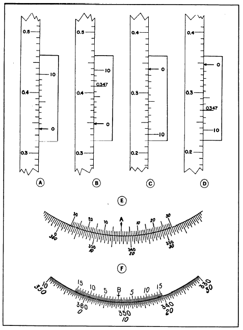
Figure 11-11.-Types of verniers.
counterclockwise angles. The slope of the numerals in the vernier to be used corresponds to the slope of the numerals in the circle being read. Care must be
taken to use the correct vernier. In figure 11-11, view E, the circle is graduated to half degrees, or 30 min. On this vernier,
30 divisions are equal in length to 29 divisions on the circle. The least reading of this vernier is 30 min divided by 30
divisions, or 1 min. The index (fig. 11-11, view E) is seen to lie between 342°30´ and 343°. In the left vernier, graduation
Number 5 is seen to coincide with a circle graduation. Then, the clockwise reading of this circle is 342°30´ plus 05´, or
342°35´. When the right vernier is used in the same way, the counterclockwise reading of the circle is 17°00´ plus 25´, or
17°25´. In figure 11-11, view F, the circle is graduated in 15-min divisions and each half of the double vernier contains
45 divisions. The least reading on this vernier is 20 sec. The clockwise reading of the circle and vernier is 351°30´plus
05´40" or 351°35´40". The counterclockwise reading is 8°15´ plus 9´20", or 8°24´20".
THEODOLITE
A theodolite is essentially a transit of high
precision. Theodolites come in different sizes and weights and from different manufacturers. Although theodolites may differ
in appearance, they are basically alike in their essential parts and operation. Some of the models currently available for
use in the military are WILD (Herrbrugg), BRUNSON, K&E, (Keuffel & Esser), and PATH theodolites.
To give you an idea of how a theodolite differs
from a transit, we will discuss some of the most commonly used theodolites in the U.S. Armed Forces.
One-Minute Theodolite
The 1-min directional theodolite is essentially
a directional type of instrument. This type of instrument can be used, however, to observe horizontal and vertical angles,
as a transit does.
The theodolite shown in figure 11-12 is a
compact, lightweight, dustproof, optical reading instrument. The scales read directly to the nearest minute or 0.2 mil and
are illuminated by either natural or artificial light. The main or essential parts of this type of theodolite are discussed
in the next several paragraphs.
HORIZONTAL MOTION.— Located on the lower portion of the alidade, and adjacent to each other, are the horizontal motion clamp and tangent
screw used for moving the theodolite in azimuth. Located on the horizontal circle casting is a horizontal circle clamp that
fastens the circle to the alidade. When this horizontal (repeating) circle clamp is in the lever-down position, the horizontal
circle turns with the telescope. With the circle clamp in the lever-up position, the circle is unclamped and the telescope
turns independently. This combination permits use of the theodolite as a REPEATING INSTRUMENT. To use the theodolite as a
DIRECTIONAL TYPE OF INSTRUMENT, you should use the circle clamp only to set the initial reading. You should set an initial
reading of 0°30´ on the plates when a direct and reverse (D/R) pointing is required. This will minimize the possibility of
ending the D/R pointing with a negative value.
VERTICAL MOTION.— Located on the standard opposite the vertical circle are the vertical motion clamp and tangent screw. The tangent screw
is located on the lower left and at right angles to the clamp. The telescope can be rotated in the vertical plane completely
around the axis (360°).
LEVELS.— The
level vials on a theodolite are the circular, the plate, the vertical circle, and the telescope level. The CIRCULAR LEVEL
is located on the tribrach of the instrument and is used to roughly level the instrument. The PLATE LEVEL, located between
the two standards, is used for leveling the instrument in the horizontal plane. The VERTICAL CIRCLE LEVEL (vertical collimation)
vial is often referred to as a split bubble. This level vial is completely built in, adjacent to the vertical circle, and
viewed through a prism and 450 mirror system from the eyepiece end of the telescope. This results in the viewing
of one-half of each end of the bubble at the same time. Leveling consists of bringing the two halves together into exact coincidence,
as
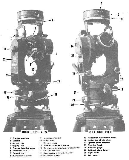
Figure 11-12.—One-minute theodolite.
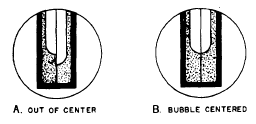
Figure 11-13.-Coincidence- type level.
shown in figure 11-13. The TELESCOPE
LEVEL, mounted below the telescope, uses a prism system and a 450 mirror for leveling operations. When the telescope
is plunged to the reverse position, the level assembly is brought to the top.
TELESCOPE.—
The telescope of a theodolite can be rotated around the horizontal axis for direct and reverse readings. It is a 28-power
instrument with the shortest focusing distance of about 1.4 meters. The cross wires are focused by turning the eyepiece; the
image, by turning the focusing ring. The reticle (fig. 11-14) has horizontal and vertical cross wires, a set of vertical and
horizontal ticks (at a stadia ratio of 1:100), and a solar circle on the reticle for making solar observations. This circle
covers 31 min of arc and can be imposed on the sun’s image (32 min of arc) to make the pointing refer to the sun’s
center. One-half of the vertical line is split for finer centering on small distant objects.
Figure 11-14.-Theodolite reticle.
The telescope of the theodolite is an inverted
image type. Its cross wires can be illuminated by either sunlight reflected by mirrors or by battery source. The amount of
illumination for the telescope can be adjusted by changing the position of the illumination mirror.
TRIBRACH.— The
tribrach assembly (fig. 11-15), found on most makes and models, is a detachable part of the theodolite that contains the leveling
screw, the circular level, and the optical plumbing device. A locking device holds the alidade and the tribrach together and
permits interchanging of instruments without moving the tripod. In a "leapfrog" method, the instrument (alidade) is detached
after observations are completed. It is then moved to the next station and another tribrach. This procedure reduces the amount
of instrument setup time by half.
CIRCLES.— The
theodolite circles are read through an optical microscope. The eyepiece is located to the right of the telescope in the direct
position, and to the left, in the reverse. The microscope consists of a series of lenses and prisms that bring both the horizontal
and the
Figure 11-15.-Three-screw leveling head.
vertical circle images into a single field of view.
In the DEGREE-GRADUATED SCALES (fig. 11-16), the images of both circles are shown as they would appear through the microscope
of the 1-min theodolite. Both circles are graduated from 0° to 360° with an index graduation for each degree on the main scales.
This scale’s graduation appears to be superimposed over an auxiliary that is graduated in minutes to cover a span of
60 min (1°). The position of the degree mark on the auxiliary scale is used as an index to get a direct reading in degrees
and minutes. If necessary, these scales can be interpolated to the nearest 0.2 min of
arc.
The vertical circle reads 0° when the
theodolite’s telescope is pointed at the zenith, and 180° when it is pointed straight down. A level line reads 90° in
the direct position and 2700 in the reverse. The values read from the vertical circle are referred to as ZENITH
DISTANCES and not vertical angles. Figure 11-17 shows how these zenith distances can be converted into vertical angles.
Figure 11-16.-Degree-graduated scales.
Figure 11-17.-Converting zenith distances into vertical angles (degrees).
In the MIL-GRADUATED SCALES (fig.
11-18), the images of both circles are shown as they would appear through the reading micro-scope of the 0.2-mil theodolite.
Both circles are graduated from 0 to 6,400 mils. The main scales are marked and numbered every 10 mils, with the
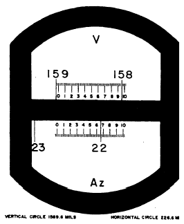
Figure 11-18.-Mil-graduated scales.
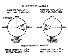
Figure 11-19.-Vertical angles from zenith distances (mils).
last zero dropped. The auxiliary scales are graduated from 0 to 10 roils in 0.2-mil increments. Readings on the auxiliary scale can be interpolated to 0.1 mil. The vertical
circle reads 0 mil when the telescope is pointed at the zenith, and 3,200 mils when it is pointed straight down. A level line
reads 1,600 roils in the direct position and 4,800 roils in the reverse. The values read are zenith distances. These zenith
distances can be converted into vertical angles as shown in figure 11-19.
One-Second Theodolite
The 1-sec theodolite is a precision direction type of instrument for
observing horizontal and vertical directions. This instrument is similar to,
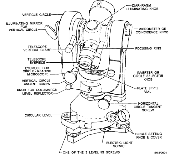
Figure 11-20.-A 1-second theodolite.
but slightly larger than, the 1-min theodolite. The WILD theodolite shown
in figure 11-20 is compact, lightweight, dustproof, optical reading, and tripod-mounted. It is one spindle, one plate level,
a circular level, horizontal and vertical circles read by an optical microscope directly to 1 sec (0.002 roil), clamping and
tangent screws for controlling the motion, and a leveling head with three foot screws. The circles are read using the coincidence
method rather than the direct method. There is an inverter knob for reading the horizontal and vertical circles independently.
The essential parts of a l-see theodolite are very similar to that of the 1-min theodolite, includ-ing the horizontal and
vertical motions, the levels, the telescope, the tribrach, and the optical system shown in figure 11-21. The main difference
between the two types, besides precision, is the manner in which the circles are read.
The CIRCLE to be viewed in the 1-see theodolite is selected by turning
the inverter knob on the right standard. The field of the circle-reading microscope shows the image of the
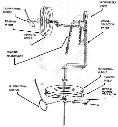
Figure 11-21.-Circle-reading optical system.
circle (fig. 11-22) with lines spaced at 20-min intervals, every third
line numbered to indicate a degree, and the image of the micrometer scale on which the unit minutes and seconds are read.
The numbers increase in value (00 to 360 0 , clockwise around the circle. The coincidence knob on the
side of, and near the top of, the right standard is used in reading either of the circles. The collimation level and its tangent
screw are used when the vertical circle is read. The circles of the theodolite are read by the COINCIDENCE METHOD in which
optical coincidence is obtained between diametrically opposite graduations of the circle by turning the MICROMETER or COINCIDENCE
KNOB. When this knob is turned, the images of the opposite sides of the circle appear to move in opposite directions across
the field of the CIRCLE-READING MICROSCOPE. The graduations can be brought into optical coincidence and appear to form continuous
lines crossing the dividing line. An index mark indicates the circle graduations that are to be used in making the coincidence.
The index mark will be either in line with a circle graduation or midway between two graduations. The final coincidence adjustment
should be made between the graduations in line with the index mark or when this index mark is halfway between the two closest
graduations.
HORIZONTAL CIRCLE.— To read
the HORIZONTAL CIRCLE, turn the INVERTER or CIRCLE-SELECTOR KNOB until its black line is horizontal. Adjust the illuminating
mirror to give uniform lighting to both sections of the horizontal circle; the micrometer scale is viewed through the circle-reading
microscope. Focus the microscope eyepiece so that the graduations are sharply defined. The view through the microscope should
then be similar to figure 11-22, view A. From this point, continue in the following
way:
1. Turn the coincidence knob until the images of the opposite sides of the circle are moved into coincidence. Turning this knob also moves
the micrometer scale. The view through the microscope now appears
as shown in figure 11-22, view B.
2. Read the degrees and tens of minutes from the image of the circle. The nearest upright number to the left of the index mark is the
number of degrees (105). The diametrically opposite number (the number ± 1800) is 285. The number of divisions
of the circle between the upright 105 and inverted 285 gives the number of tens of minutes. In figure 11-22, view B, there
are five divisions between 105 and 285; and the reading, therefore, is 1050 50´. The index may also be used for
direct reading of the tens of minutes. Each graduation is treated as 20 min. Thus, the number of graduations from the degree
value to the index mark multiplied by 20 min is the value. If the index falls between graduations, another 10 min is added when the tens of minutes is read directly.
3. Read the unit minutes and seconds below
from the image of the micrometer scale. This scale has two rows of numbers below the graduations; the bottom row is the unit
minutes and the top row, seconds. In figure 11-22, view B, the unit minutes
and seconds are read as 7'23.5''
4. Add the values determined in Steps 2 and 3 above. This gives 1050 57'23.5''as the final reading.
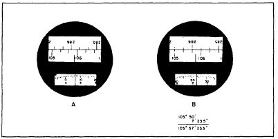
Figure 11-22.-View of a 1-second theodolite circle
VERTICAL CIRCLE.— When
reading the VERTICAL CIRCLE, turn the circle-selector knob until its black line is vertical. Adjust the mirror on the left
standard and focus the microscope eyepiece. You then go on in the following way:
1. Use the vertical circle tangent screw to move the collimation level until the
ends of its bubble appear in coincidence (fig. 11-23) in the collimation level viewer on the left standard.
2. Read the vertical circle and micrometer scale as described before. Be sure to
have proper coincidence before you take the reading.
3. The vertical circle graduations are num-bered to give a 00 reading
with the telescope pointing to the zenith. Consequently, the vertical circle reading will be 900 for a horizontal
sight with the telescope direct and 2700 for a horizontal sight with the telescope reversed. Figure 11-23 shows
the view in the circle-reading microscope for direct and reversed pointings on a target.
These readings are converted to vertical angles as follows:
There are two separate occasions for setting the horizontal circle of the theodolite.
In the first case, the circle is set to read a given value with the telescope pointed at a target. With the theodolite pointed
at the target and with the azimuth clamp tightened, the circle is set as follows: Set the micrometer scale to read the unit
minutes and the seconds of the given values. Then, with the circle-setting knob, you turn the circle until coincidence is
obtained at the degree and tens of minutes value of the given reading. This setting normally can be made accurately to plus
or minus 5 sec. After the circle is set in this manner, the actual reading should be determined.
In the second case, the circle is set to a value of a given angle. When a predetermined
angle is measured, you first point the instrument along the initial line from which the angle is to be measured and read the
circle. Add the value of the angle to the circle reading to determine the circle reading for the second pointing. Set the
micrometer scale to read the unit minutes and the seconds of the value to be set on the circle. Then, you turn the instrument
in azimuth and make coincidence at the degrees and tens of minutes value that is to be set. The predetermined value can usually
be set on the circle in this way to plus or minus 2 sec.
ENGINEER’S LEVEL
The engineer’s level is a widely used instrument
for leveling operations. Its sighting device is a 30 ± 3 variable power telescope, with a maximum length of 18 in. and with
an erecting eyepiece. Some models use internal focusing, while others use external focusing objective
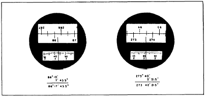
Figure 11-23.-View of a vertical circle for direct and reversal pointings.
assemblies. The reticle has two cross hairs at right
angles to each other, and some models have stadia hairs. The telescope and level bar assembly is mounted on a spindle that
permits the unit to be revolved only in a horizontal plane. It cannot be elevated or depressed. A clamp and tangent screw
acts on this spindle for small motions to permit accurate centering. The spindle mounts in a four-screw leveling head that
rests on a foot plate. The foot plate screws onto the threads on the tripod. When the instrument is properly leveled and adjusted,
the line of sight, defined by the horizontal cross hair, will describe a horizontal plane.
The two distinct types of engineer’s levels,
classified according to their support, are the wye level and the dumpy level. The WYE LEVEL (fig. 11-24) is so called because
its telescope is supported by a pair of wye rings. These rings can be opened for the purpose of turning the telescope or rotating
it around its horizontal axis. The bubble tube (vial) can be adjusted, either vertically or laterally, by means of adjusting
nuts at the ends of the bubble tube. All these features are provided for the purpose of making fine adjustments. The DUMPY
LEVEL (fig. 11-25) has its telescope rigidly attached to the level bar, which supports an adjustable, highly sensitive level
vial. During visual leveling operations and observations, both types handle similar basic operations. Their cross hairs are
brought into focus by rotation of the eyepiece, and their target, into clear focus by rotation of the focusing knob. Their
telescope can be exactly trained on targets by lightly tightening the azimuth clamp and manipulating the azimuth tangent screw.
PRECISION LEVEL
Other types of leveling instruments have been incorporated into the
SEABEE units. In fact, the self-leveling level has now become standard
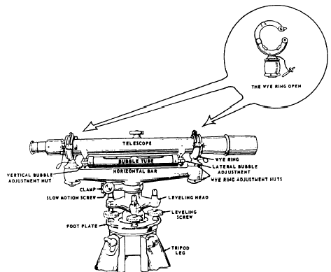
Figure 11-24.-A wye level.
equipment in the Naval Construction Force Table of Allowance (TOA). These precision
instruments are essentially like the conventional levels except for added features.
A precision level is one that is equipped with an extra-sensitive level vial. The
sensitivity of a level vial is usually expressed in terms of the size of the vertical angle the telescope must be moved to
cause the bubble in the level vial to move from one graduation to the next.
The sensitivity of the level vial on an ordinary level is about 20 sec. On a precise
level, it is about 2 sec. The telescope level vial on an ordinary transit has a sensitivity of about 30 sec.
The more sensitive the level vial is, the more difficult it is to center the bubble.
If the level vial on an ordinary level had a sensitivity as high as 2 sec, the smallest possible movement of the level screw
would cause a large motion of the bubble. For this reason, a precise level is usually also a tilting level. On a tilting level,
the telescope is hinged at the objective end so the eyepiece end can be raised or lowered. The eyepiece end rests on a finely
threaded micrometer screw that can be turned to raise or lower the eyepiece end in small increments. The instrument is first
leveled, as nearly as possible, in the usual manner. The bubble is then brought to exact center by the use of the micrometer
screw.
Military Level
The military level (fig. 11-26) is a semi-precise level designed for a more precise work than the engineer’s level. The telescope is
a 30-power, 10-in.-long, interior-focusing type with an inverting eyepiece and an enclosed fixed reticle. The reticle is mounted
internally and cannot be adjusted as in other instruments. It contains cross wires and a set of stadia hairs. The objective
is focused by an internal field lens through a rack and pinion, controlled by a knob on the upper right-hand side of the telescope.
The telescope and level vial can be tilted through a small angle in the vertical plane to make the line of sight exactly horizontal just before the rod reading is made.
The tilting is done by a screw with a graduated
drum located below the telescope eyepiece. A cam is provided to raise the telescope off of the tilting device and to hold
it firmly when the instrument is being moved and during the preliminary
Figure 11-26.-A military level.
leveling. An eyepiece, located to the left of the
telescope, is used for viewing the bubble through the prism system that brings both ends of the bubble
(fig. 11-13) into coincidence.
The level vial is located directly under the
telescope, but to the left and below, directly in line with the capstan screws under the bubble-viewing eyepiece. The level
vial’s sensitivity is given as 30 sec per 2-mm spacing. A circular bubble that is viewed through a 450 mirror
is provided for the first approximate leveling before the long level vial is used. For night work, battery-powered electric
illumination lights the long bubble, the reticle, and the circular level. The clamping screw and the horizontal motion tangent
screw are located on the right-hand side; the former near the spindle and the latter below the objective lens. The instrument
has a three-screw leveling head. The tripod for this level has a non-extension leg to add rigidity and stability to the setup.
Self-Leveling Level
The self-leveling level (also called automatic level) shown in figure
11-27 is a precise, time-saving development in leveling instruments. It did away with the tubular spirit level, whose bubble
takes time in centering as well as in resetting its correct position from time to time during operation.
The self-leveling level is equipped with a small bull’ s-eye level and three
leveling screws. The leveling screws, which are on a triangular foot plate, are used to center the bubble of the bull’s-eye
level approximately. The line of sight automatically becomes horizontal and remains horizontal as long as the bubble remains
approximately centered. A prismatic device called a compensator makes this possible. The compensator is suspended on fine,
nonmagnetic wires. The action of gravity on the compensator causes the optical system to swing into the position that
Figure 11-27.-An automatic level.
defines a horizontal sight. This horizontal line of sight is maintained despite a
slight out of level of the telescope or even when a slight disturbance occurs on the instrument.
HAND LEVEL
The hand level, like all surveying levels, is an instrument that combines
a level vial and a sighting device. It is generally used for rough leveling work. In a cross-sectional work, for example,
terrain irregularities may cause elevations to go beyond the instrument range from a setup. A hand level is useful for extending
approximate elevations off the control survey line beyond the limits of the instruments. Figure 11-28, view A, shows a LOCKE
HAND LEVEL; view B shows an ABNEY HAND LEVEL.
For greater stability, both hand levels may be rested against a tree, rod, range
pole, or on top of a staff. A horizontal line, called an index line, is provided in the sight tube as a reference line. The
level vial is mounted atop a slot in the sight tube in which a reflector is set at a 45° angle. This permits the observer,
while sighting through the tube, to see the landscape or object, the position of the bubble in the vial, and the index line
at the same time.
The distances over which a hand level is sighted are comparatively short; therefore,
no magnification is provided for the sighting.
The Abney hand level is more specialized than the Locke type. It has a clinometer
for measuring the vertical angle and the percent of grade. The clinometer has a reversible graduated arc assembly mounted
on one side. The lower side of the arc is graduated in degrees, and the upper side, in percent of slope. The level vial is
attached to the axis of rotation at the index arm. When the index arm is set at zero, the clinometer is used like a plain
hand level. The bubble is centered by moving the arc and not the sighting tube as is the case in the plain hand level. Thus,
the difference between the line of sight and the level bubble axis can be read in degrees or percent of slope from the position
of the index arm of the arc. The 45° reflector and the sighting principle with its view of the landscape, bubble, and index
line are the same as in the plain hand level.
Figure 11-28.-Types of hand levels.
PLANE TABLE
When combined with the stadia board or
Philadelphia rod, the plane table are used in what is generally known as plane table surveys. Which these instruments, the
direction, the distance, and the difference in elevation can be measured and plotted directly in the field. The plane table
opration produces a completed sketch or map manuscript without the need for further
plotting or computing.
A plane table (fig. 11-29) consists of a drawing
board mounted on a tripod with a leveling device designed as part of the board and tripod. The commonly used leveling head
is the ball-and-socket type. The cross section of a plane table with the tripod head is shown in figure 11-30. The board (G)
usually is either 18 by 24 in. or 24 by 31 in. and has an attached recessed fitting that screws onto the top of the spindle
(A). A wingnut (B) controls the grip of parts C and D on cup E. By releasing the wingnut (B), you can tilt the drawing board
in any direction to level it. Another wingnut (F) acts only on the spindle and, when released, permits the leveled board to
be rotated on azimuth for orientation. The tripod is shorter than the transit or level tripods and, when set up, brings the
plane table about waist high for easy plotting. One precaution must be observed
in attaching the plane table to the tripod head.
A paper gasket should be placed between the fittings to
prevent sticking or "freezing" of the threads. The plane table is setup over a point on the ground whose position has been
previously plotted, or will be
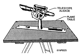
Figure 11-29.-Plane table.
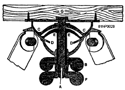
Figure 11-30.-Cross section of a plane table tripod bead.
plotted, on the plane table sheet during the operation.
The board is oriented either by using a magnetic compass for north-south orientation or by sighting on another visible point
whose position is plotted. The board is clamped and the alidade is pointed toward any new, desired point using the plotted
position of the setup ground station as a pivot. A line drawn along the straightedge that is parallel to the line of sight
will give the plotted direction from the setup point to the desired point. Once the distance between the points is determined,
it is plotted along the line to the specified scale. The plotted position represents the new point at the correct distance
and direction from the original point. By holding the plane table orientation and pivoting the alidade around the setup point,
you can quickly draw the direction to any number of visible points. The distance to these points is determined by any conventional
method that meets the requirements for the desired accuracy and can be plotted along their respective rays from the setup
point. Thus, from one setup, the positions of a whole series of points can be established quickly. For mapping, the difference
in elevation is also determined and plotted for each point. The map is completed by subdividing the distances between points
with the correct number of contours spaced to represent the slope of the ground.
The alidade (fig. 11-31) is a straightedge with a sighting device parallel to the
edge. The more precise types have telescopes for sighting, special retitles for
measuring distance, and graduated arcs for measuring vertical angles. A new version also includes a self-leveling, optical-reading
system with enclosed graduated arcs.
1. The open-sight alidade (fig. 11-31, view A),
which is very useful in sketching small areas, has a collapsible open sight attached to a straightedge. A level bubble is
mounted on the straightedge for keeping the alidade level. A trough compass is also furnished for attaching to the sketch
board. By sighting through the peep sight, the operator can determine a level line and the slope from the sighting point.
No magnification is provided, so the sight lines are kept comparatively short. The distances can be estimated by pacing or
can be measured with a tape if more accuracy is required. A 10-mil graduation that is numbered every fifth tick mark from
0 to 40 runs up on the right edge and down on the left edge of the front sight
for determining slopes.
2. The telescopic alidades (fig. 11-31, views B and
C) consist of straightedges with rigidly mounted telescopes that can be rotated through a vertical angle of ±30 0 . One type
has a telescope set on a high standard or post to raise it above the table. This permits direct viewing through the telescope,
which is at a comfortable height. The other type has the telescope mounted close to the straightedge. A right-angle prism
is attached to the eyepiece and permits viewing through the telescope by looking down into the
eyepiece prism.
3. The telescope for the high standard is 16 power; for the low standard, 12 power.
Both are the inverting type with internal focusing. The prismatic eyepiece inverts
the image top to bottom, so that it appears erect but reversed side to side. The line of sight through the telescopes in a
level position is parallel to the straightedge on the base. The telescope reticle has horizontal and vertical cross hairs
and a set of stadia hairs. As you already knew, the stadia hairs are used to measure distances. The vertical distance between
the upper and lower stadia hairs is carefully read and multiplied by the stadia interval factor. This value is the straight-line
distance between the instrument and the rod.
4. A circular bubble and a magnetic compass
needle are attached to the base. These are used to level the plane table and orient it to its proper position. Since the ball-and-socket
head does not permit as fine a movement as the leveling screw, the bubble is centered as accurately as possible. Then, the
wingnut (fig. 11-30, view B) is set firmly but not tightly. When the plane table is tapped lightly on the proper corner, the
operator can refine the leveling and then properly tighten the wingnut. To orient the plane table, loosen wingnut F and rotate
the table. It is a good practice to draw a magnetic north line on the cover sheet or on two pieces of tape attached near the
edges of the board. The straightedge is set on this line during orientation. When the plane table is rotated to face north,
the magnetic needle is released and will have room to swing in its case without hitting
the sides.
5. The telescopic alidades have two other
important features used for plane table surveying. These are the detachable striding level and the
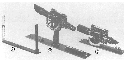
Figure 11-31.-Types of alidades.
stadia arc. The striding level contains a long
bubble, and when attached, permits accurate leveling of the line of sight. The bubble is mounted on a metal tube with V-fittings
on each end. The fittings are placed astride the telescope and bear on built-in polished brass rings on each side of the center
post. A spring clip on the level grips a center pin on top of the telescope and keeps the level from falling or being knocked
off during operation. A button on the side of the level releases the clip for removing the level. For checking and adjusting,
the level is reversible. The striding level normally is used to establish a horizontal line of sight and to use the alidade
as a level. The stadia arc assembly consists of a vertical arc mounted on the end of the left trunnion and a vernier attached
to the left bearing by an arm. A level vial is attached to the upper end of the arm; a tangent screw controls the movement
of the vial. Once adjusted, this vial establishes a reference from which vertical angles can be measured even if the plane
table is not exactly level. The stadia arc is a vertical scale attached to the alidade. With the stadia arc, it is possible
to determine horizontal distances and differences in elevation by the stadia
method.
6. A new model telescopic alidade is the
self-leveling, optical-reading instrument. Instead of the exterior arc and level bubble, a prism system with a suspended element
and enclosed arcs is used. As long as the alidade base is leveled to within one-half degree of horizontal, the suspending
element (or pendulum) will swing into position. Then the vertical arc index that is attached to it will assume a leveled position.
The scales are read directly through an optical train. This combination permits faster operation. In addition, there is no
chance of forgetting to index the arc bubble and introducing errors into the readings.
Some of the auxiliary equipment used with a
plane table consists of a coated plastic or a paper plane table sheet on which the map or sketch is drawn, drawing materials
(scribing tools for coated plastic or pencils for the paper), scales for plotting distances, triangles, waterproof table covers,
umbrella, and notebook. The plane table sheet is attached to the board by flatheaded, threaded studs that fit into recesses
in the table and do not obstruct the alidade’s movement.
FIELD EQUIPMENT
The term field
equipment, as used in this training manual, includes all devices, tools, and instrument accessories used in connection
with field measurements.
FIELD TOOLS
If you are running a survey across rough
terrain, the essential equipment you will need are various types of tools used for clearing the line; that is, for cutting
down brush and other natural growth as necessary.
Surveying procedures usually permit the
bypassing of large trees. Occasionally, however, it may be necessary to fell one of these. If heavy equipment is working in
the vicinity, an EO may fell the tree with a bulldozer. The next best method is by means of a power-driven chain saw. In the
absence of a chain saw, a one-man or two-man crosscut saw may be available. The machete and brush hook (fig. 11-32) are used
for clearing small saplings, bushes, vines, and similar growth. Axes and hatchets (fig. 11-32) are used
for felling trees and also for marking trees
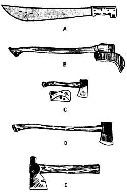
Figure 11-32.-(A) Machete; (B) Brush hook; (C) Single-bit
belt ax; (D) Single-bit ax; (E) Half hatchet.
by blazing. Files and stones are usual items of equipment
for sharpening the edges of tools. Hubs, stakes, pipe, and other driven markers are often driven with the driving peen of
a hatchet or a single-bit ax. A sledgehammer, however, is a more suitable tool for the purpose. A double-faced, long-handled
sledgehammer is shown in figure 11-33. It is swung with both hands. There are also short-handled sledgehammers, swung with
one hand. A sledgehammer is classified according to the weight of the head; common weights are 6, 8, 10, 12, 14, and 16 lb.
The 8- and 10-lb weights are most commonly used. When the ground is too compact or too frozen to permit wooden stakes and
hubs to be driven directly, the way for a stake or hub is opened by first driving in a heavy, conical-pointed steel bar, 10
to 16 in. long, called a bull-point. One of the heavy steel form pins, used to pin down side forms for concrete paving, can
be used as a bull-point; however, the pyramidal pavement-breaker bit on a jack hammer (pneumatic hammer used to drive paving
breaker bits, stone drills, and the like) makes a better bull-point. Because a jack hammer bit is made of high-carbon steel,
it is liable to chip and mushroom when subjected to heavy pounding. Do not use a bull-point with a badly damaged head; it
should be refinished by grinding or cutting off before being used to avoid injury to
personnel.
In searching for hidden markers, you may
need a shovel like the one shown in figure 11-34 for clearing top cover by careful digging. In soft ground, such as loose,
sandy soil, you may prefer to use a square-pointed shovel or a probing steel rod to locate buried markers.
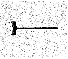
Figure 11-33.-A double-faced sledgehammer.
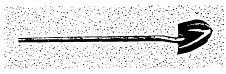
Figure 11-34.-Long-handled shovel.
A pick (fig. 11-35) may be required to chip
bituminous pavement off of manhole covers and for levering up covers. Sometimes a crowbar is needed
for levering manhole covers.
Buried metal markers may be located with the
help of a magnetic device called a dip needle or a battery-powered instrument, similar in principle to a mine detector, commonly
called a pipe finder. These instruments are used in engineering surveys to locate utility pipelines, buried manhole and valve
box covers, and the like. These instruments can generally be borrowed from the utilities division of the public works department
(PWD) of the larger shore stations.
SURVEYING TAPES
Tapes are used in surveying to measure
horizontal, vertical, and slope distances. They may be made of a ribbon or a band of steel, an alloy of steel, cloth reinforced
with metal, or synthetic materials. Tapes are issued in various lengths and widths and graduated in a variety of ways.
Metallic Tapes
A metallic tape is made of high-grade synthetic
material with strong metallic. strands (bronze-brass- copper wire) woven in the warped face of the tape and coated with a
tough plastic for
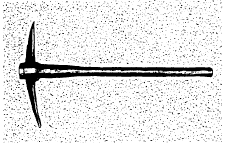
Figure 11-35.-Pick.
durability. Standard lengths are 50 and 100 ft.
Some are graduated in feet and inches to the nearest one-fourth in. Others are graduated in feet and decimals of a foot to
the nearest 0.05 ft. Metallic tapes are generally used for rough measurements, such as cross-sectional work, road-work slope
staking, side shots in topographic surveys, and many others in the same category. Nonmetallic tapes woven from synthetic yarn,
such as nylon, and coated with plastic are available; some surveyors prefer to use tapes of this type. Nonmetallic tapes are
of special value to power and utility field personnel, especially when they are working in the vicinity of high-voltage circuits.
Steel Tapes
For direct linear measurements of ordinary or
more accurate precision, a steel tape is required. The most commonly used length is 100 ft, but tapes are also available in
50-, 200-, 300-, and 500-ft lengths. All tapes except the 500-ft one are band-types, the common band widths being 1/4 and
5/16 in. The 500-ft tape is usually a flat-wire type.
Most steel tapes are graduated in feet and
decimals of feet, but some are graduated in feet and inches, meters, Gunter’s links, and chains or other linear units.
From now on, when we discuss a tape, we will be talking about one that is graduated in feet and decimals of a foot unless
we state otherwise.
Some tapes called engineer’s or direct reading
tapes are graduated throughout in subdivisions of each foot. The tape most commonly used, however, is the so-called chain
tape, on which only the first foot at the zero end of the tape is graduated in subdivisions, the main body of the tape being
graduated only at every 1-ft mark. A steel tape is sometimes equipped with a reel on which the tape can be wound. A tape can
be, and often is, detached from the reel, however, for more convenient use in
taping.
Various types of surveying tapes are shown in
figure 11-36. View A shows a metallic tape; view B, a steel tape on an open reel; view C, a steel tape or, a closed reel.
View D shows a special type of low-expansion steel tape used in high-order work; it is generally called an Invar tape or Lovar
tape.
Invar Tapes
Nickel-steel alloy tapes, known as Invar,
Nilvar, or Lovar, have a coefficient of thermal
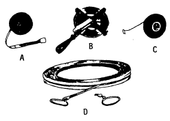
Figure 11-36.-Surveying tapes.
expansion of about one-tenth to one-thirtieth (as
low as 0.0000002 per 10 F) that of steel. These tapes are used primarily in high-precision taping. These tapes
must be handled in exactly the same manner as other precise surveying instruments. The alloy metal is relatively soft and
can be easily broken or kinked if mishandled. Ordinarily, Invar tapes should not be used when a steel tape can give the desired
accuracy under the same operating conditions. Invar tapes are used for very precise measurements, such as those for base lines
and in city work. When not in use, the tape should be stored in a reel, as shown in figure 11-36, view D. Except for special
locations where the ground surface is hard and flat, such as roadways or railroads beds, the Invar tape is used over special
supports or stools and is not permitted to touch the ground.
SURVEYING ACCESSORIES
Surveying accessories include the equipment,
tools, and other devices used in surveying that are not considered to be an integral part of the surveying instrument itself.
They come as separate items; thus, they are ordered separately through the Navy
supply system.
When you run a traverse, for example, your
primary instruments may be the transit and the steel tape. The accessories you need to do the actual measurement will be the
following: a tripod to support the transit; a range pole to sight on in line; a plumb bob to center the instrument on the
point; perhaps tape supports if the survey is of high precision; and so forth. It is important that you become familiar with
the proper care of this equipment and use it properly.
Tripod
The tripod is the base or foundation that
supports the survey instrument and keeps it stable during observations. A tripod consists of a head to which the instrument
is attached, three wooden or metal legs that are hinged at the head, and pointed metal shoes on each leg to be pressed or
anchored into the ground to achieve a firm setup. The leg hinge is adjusted so that the leg will just begin to fall slowly
when it is raised to an angle of about 450. The tripod head may have screw threads on which the instrument is mounted
directly, a screw projecting upward through the plate, or a hole or slot through which a special bolt
is inserted to attach to the instrument.
Two types of tripods are furnished to
surveyors: the fixed-leg tripod and the extension-leg tripod. The fixed-leg type is also called a STILT-LEG or RIGID tripod,
and the extension-leg tripod is also called a JACK-LEG tripod. Both types are shown in figure 11-37. Each fixed leg may consist
of two lengths of wood as a unit or a single length of wood split at the top, attached to
a hinged tripod head fitting and to a metal shoe.
At points along the length, perpendicular brace
pieces are sometimes added to give greater stability. The extension tripod leg is made of two sections that slide longitudinally.
On rough ground, the legs are adjusted to different lengths to establish a horizontal tripod head or to set the instrument
at the most comfortable working height for the observer. A leg may be shortened and set as shown in the extreme right view
of figure 11-37.
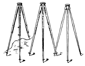
Figure 11-37.-Types of tripods.
The fixed legs must be swung in or out in
varying amounts to level the head. Instrument height is not easily controlled, and the observer must learn the correct spread
of the legs to get the desired height.
WIDE-FRAME tripods, like those shown in
figure 11-38, have greater torsional stability and tend to vibrate less in the
wind.
You should grip the surveying instrument
firmly to avoid dropping it while you are mounting it on the tripod. Hold the transit by the right standard (opposite the
vertical circle) while you are attaching it. The engineer’s level should be held at the center of the telescope, while
theodolites and precise levels should be gripped near the base of the instrument. The instruments should be screwed down to
a firm bearing but not so tightly that they will bind or the screw threads will
strip.
In setting up the tripod, you should be sure
to place the legs so that you achieve a stable setup. On level terrain, you can achieve this by having each leg form an angle
of about 600 with the ground surface.
Loosen the restraining strap from around the
three legs, and secure it around one leg. An effective way to set the tripod down is to grip it with two of the legs close
to the body while you stand over the point where the setup is required. By using one hand, you push the third leg out away
from the body until it is about 50° to 60° with a horizontal. Lower the tripod until the third leg is on the ground. Place
one hand on each of the first two legs, and spread them while taking a short backward step, using the third leg as a
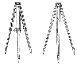
Figure 11-38.-Wide-frame tripods.
pivot point. When the two legs look about as far
away from the mark as the third one and all three are about equally spaced, you lower the two legs and press them into the
ground. Make any slight adjustment to level the head further by moving the third leg a few inches in or out before pressing
it into the ground.
On smooth or slippery paved rock surfaces,
you should tighten the tripod legs hinges while setting up to prevent the legs from spreading and causing the tripod to fall.
You should make use of holes or cracks in the ground to brace the tripod. In some cases, as a safety factor, you should tie
the three legs together or brace them with rock or bushes after they are set to keep them from spreading. If setups are to
be made on a slippery finished floor, rubber shoes may be fitted to the metal shoes, or an equilateral triangle leg retainer
may be used to prevent the legs from sliding.
When you are setting up on steeply sloping
ground, place the third leg uphill and at a greater distance from the mark. Set the other two legs as before, but before releasing
them, check the stability of the setup to see that the weight of the instrument and tripod head will not overbalance and cause the tripod to slip or fall.
Proper care must be observed in handling the
tripod. When the legs are set in the ground, care must be taken to apply pressure longitudinally. Pressure across the leg
can crack the wooden pieces. The hinge joint should be adjusted and not overtightened to the degree that it would cause strain
on the joint or strip or lock the metal threads. The machined tripod head is to be kept covered with the head cover or protective
cap when not in use, and the head should not be scratched or burred by mishandling. When the tripod is in use, the protective
cap is to be placed in the instrument box to prevent it from being misplaced or damaged. Any damage to the protective cap
can be transferred to the tripod head. Mud, clay, or sand adhering to the tripod has to be removed, and the tripod is to be
wiped with a damp cloth and dried. The metal parts should be coated with a light film of oil or wiped with an oily cloth.
Foreign matter can get into hinged joints or on the machined surfaces and cause wear. Stability is the tripod’s greatest
asset. Instability, wear, or damaged bearing surfaces on the tripod can evolve into unexplainable errors in the final survey
results.
Range Pole
A range pole (also called a lining rod) is a
wood or metal pole, usually about 8 ft long and about 1/2 to 1 in. in diameter; it is provided with a steel point or shoe
and painted in alternate bands of red and white to increase its visibility. Figure 11-39 shows a variety of range poles. The
range pole is held vertically on a point or plumbed over a point, so the point may be observed through an optical instrument.
It is primarily used as a sighting rod for either linear or angular measurements. For work of ordinary precision, chainmen
may keep on line by observing a range pole. A range pole may also be used for approximate stadia measurement.
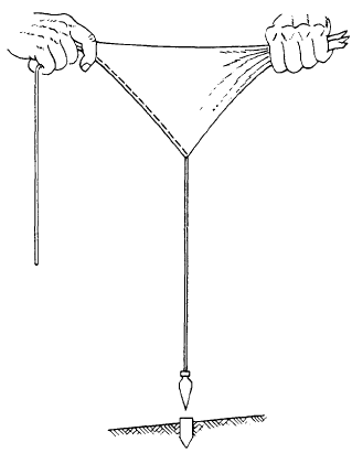
Plumb Bob, Cord, and Target
A plumb bob is a pointed, tapered brass or
bronze weight that is suspended from a cord for the general purpose of determining the plumb line from a point on the ground.
Common weights for
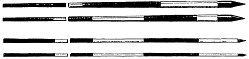
Figure 11-39.-Range poles.
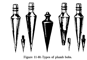
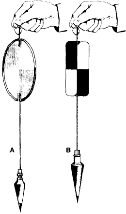
Figure 11-41.-Plumb bob, cord, and target.
plumb bobs are 6, 8, 10, 12, 14, 16, 18, and 24
OZ; the 12- and the 16-oz are the most popular. Typical plumb bobs are shown in figure 11-40. A plumb bob is a precision instrument
and must be cared for as such. If the tip becomes bent, the cord from which the bob is suspended will not occupy the true
plumb line over the point indicated by the tip. A plumb bob usually has a detachable tip, as shown in figure 11-40, so if
the tip becomes damaged, it can be renewed without replacing the entire instrument.
Each survey party member should be equipped
with a leather sheath, and the bob should be placed in the sheath whenever it is not in use. The cord from a plumb bob can
be made more conspicuous for observation purposes by the attachment of an oval form aluminum target (fig. 11-41, view A).
The oval target has reinforced edges, and the face is enameled in quadrants alternately with red and white. Also, a flat rectangular
plastic target may be used (fig. 11-41, view B). It has rounded corners with alternate red and white quadrants on its face.
These plumb bob string targets are pocket size with approximate dimensions of 2 by 4 in.
Optical Plumbing Assembly
The optical plumbing assembly, or plummet, is a device built
into the alidade or the tribrach of some of the instruments to center the instrument over a point. Its working principle is
shown in figure 11-42. The plummet consists of a small prismatic telescope with a cross wire or
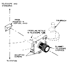
Figure 11-42.-Optical plumbing assembly.
Figure 11-43.-Types of tape clamp handles.
marked circle reticle adjusted to be in line with the vertical axis of the instrument.
After the instrument is leveled, a sighting through the plummet will check the centering over a point quickly. The advantages
of the plummet over the plumb bob are that it permits the observer to center over a point from the height of the instrument
stand, and it is not affected by the wind. The plummet is especially useful for work on high stands. A plumb bob requires
someone at ground level to steady it and to inform the observer on the platform how to move the instrument and when it is
exactly over the point. With the plummet, the centering and checking is done by the observer.
Tape Accessories
There is usually a leather thong at each end
of a tape, by which the tape can be held when the full length is being used. When only part of the tape is used, the zero
end can be held by the thong, and the tape can be held at an intermediate point by means of a tape clamp handle, like those
shown in figure 11-43.
When a tape is not supported throughout— that is, when it is held aboveground
between a couple of crew members—a correction must be applied for the amount
of sag in the tape. To make this correction, you apply a certain amount of tension. Figure 11-44 shows two devices for applying
a given amount of tension.
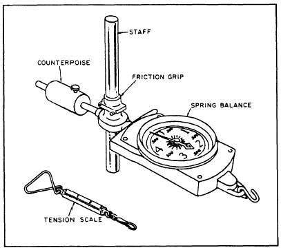
Figure 11-44.-Tension scale and spring balance.
The tension scale is graduated in pounds from
0 to 30. It is clipped to the eye at the end of the tape, and the tension is applied until the desired reading appears on
the scale. A pair of staffs can be used’ to make the work easier. The rawhide thongs are wrapped around the staff at
a convenient height and gripped firmly. The bottom end of the staff is braced against the foot (fig. 11-45) and the upper
end tucked under the arm. Tension is applied by using the shoulder and leaning against the poles. The spring balance is used
in a similar fashion for work of higher precision.
The stool device in figure 11-45 is called a
tapping stool or chaining buck and is used in high-precision work. It is a metal three-legged stand with an adjustable sliding
head and a hand wheel operated device for locking the plate (the top surface of the sliding head) in any desired position.
A line is scribed on the plate. During taping operations, the head is moved until the scribed line is directly under a particular
graduation on the tape; the handwheel is then used to lock the head. When the tape is shifted ahead to measure the next interval,
the graduation is held exactly over the line until the next stool is adjusted and locked. The basic purpose of taping stools
is to furnish stable, elevated surfaces on which taped distances can be marked accurately. When stools are not available,
2 by 4s or 4 by 4s are often driven into the ground for use as chaining bucks.
The length of a tape varies with the temperature,
and the precision of a survey may require the application of corrections for this. For work of ordinary precision, you can
assume that the
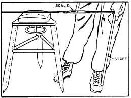
Figure 11-45.-Applying tension to tape.

Figure 11-46.-Tape thermometer.
temperature of the tape is about the same as that
of the air. For work requiring higher precision, a tape thermometer, like the one shown in figure 11-46, is attached to the
tape. For very precise work, two thermometers, one positioned at each end, may be used. If the two indicate different temperatures,
the mean between them is calculated and used.
Chaining Pin
A chaining pin (also called a taping arrow) is
a metal pin about 1 ft long. It has a circular eye at one end and a point for pushing it into the ground at the other (fig.
11-47). These pins come in sets of 11 pins, carried on a wire ring passed through the eyes in the pins or in a sheath called
a quiver.
Chaining pins can be used for the temporary
marking of points in a great variety of situations, but they are used most frequently to keep count of tape increments in
the chaining of long distances.
Leveling Rod, Target, and Rod Level
A leveling rod, in essence, is a tape supported
vertically and is used to measure the vertical distance (difference in elevation) between a line
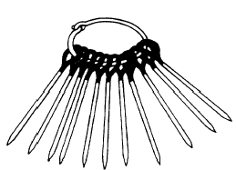
Figure 11-47.-Taping arrows or chaining pins.
of sight and a required point above or below it.
This point may be a permanent elevation (bench mark), or it may be some natural or constructed surface.
There are several types of leveling rods. The
most popular of all is the Philadelphia rod, as shown in figure 11-48. it is a graduated wooden rod made of two sections and
can be extended from 7 to 13 ft. In view A, each foot is subdivided into hundredths of a foot. Instead of each hundredth being
marked with a line or tick, the distance between alternate ones is painted black on a white background. Thus, the value for
each hundredth is the distance between the colors; the TOP of the black, EVEN values, the BOTTOM of the black, ODD values.
The tenths are numbered in black, the feet in red. This rod may be used with the level, transit, theodolite, and with the
hand level on occasion to measure the difference in elevation.
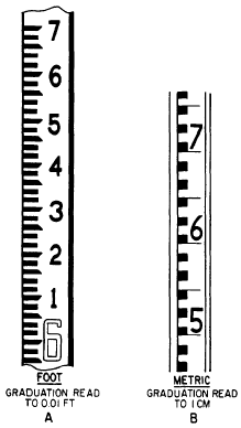
Figure 11-48.-Philadelphia rod.
The leveling rod may be read directly by the
instrumentman sighting through the telescope, or it may be target-read. Conditions that hinder direct reading, such as poor
visibility, long sights, and partially obstructed sights, as through brush or leaves, sometimes make it necessary to use targets.
The target is also used to mark a rod reading when numerous points are set to the same elevation
from one instrument setup.
Targets for the Philadelphia rod are usually
oval, with the long axis at right angles to the rod, and the quadrants of the target painted alternately red and white. The
target is held in place on the rod by a C-clamp and a thumbscrew. A lever on the face of the target is used for fine adjustment
of the target to the line of sight of the level. The targets have rectangular openings approximately the width of the rod
and 0.15 ft high through which the face of the rod may be seen. A linear vernier scale is mounted on the edge of the opening
with the zero on the horizontal line of the target for reading to thousandths of a foot. When the target is used, the rodman
takes the rod reading.
The other types of leveling rods differ from
the Philadelphia rod only in details. The Frisco rod, for direct reading only, is available with two or three sliding sections.
The Chicago rod is available with three or four sections that, instead of sliding, are joined at the end to each other like
a fishing rod. The architect’s or builder’s rod is a two-section rod similar to the Philadelphia but is graduated
in feet and inches to the nearest one-eighth in. rather than decimally. The upper section of the Lenker self-computing rod
has the graduations on a continuous metal belt that can be rotated to set any desired graduation at the level of the height
of the instrument (HI). To use the rod, you set the rod on the bench mark and bring the graduation that indicates the elevation
of the bench mark level with the HI. As long as the level remains at that same setup, wherever you set the rod on a point,
you read the elevation of the point directly. In short, the Lenker rod does away with the
necessity for computing the elevations.
View B (fig. 11-48) shows the rod marked with
metric measurements; the graduations of the rod are in meters, decimeters, and centimeters. The targets that are furnished
with the metric rod have a vernier that permits reading the scale to the nearest millimeter. The metric rod can be extended
from 2.0 to 3.7 meters.
For high-precision leveling, there are precise
leveling rods as well as precise engineer’s levels. A Lovar rod is usually T-shaped in cross section
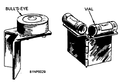
Figure 11-49.-Types of rod levels.
and has the scale inscribed on the strip of Lovar metal.
A precise rod usually has a tapering, hardened steel base. Some are equipped with thermometers, so temperature correction
can be applied. Precise rods generally contain built-in rod levels.
When a rod reading is made, it is accurate only if
the rod is perfectly plumbed. If it is out of plumb, the reading will be greater that the actual vertical distance between
the HI and the base of the rod. Therefore, to ensure a truly plumbed leveling rod, use a rod level. Two types of rod levels
that are generally used with standard leveling rods are shown in figure 11-49. The one at the left is called the bull’s-eye
level, and one on the right is the vial level. Figure 11-50 shows the proper way of using the bull’s-eye level; the
vial level is attached in the same manner.
Proper care should be taken of leveling rods. The
care consists of keeping them clean, free of sand and dirt, unwarped, and readable. They must be carried over
the shoulder or under the arm from point to point.
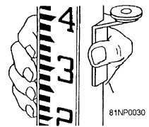
Figure 11-50.-Proper attachment of a bull’s-eye rod level to the rod.
Dragging them through the brush or along the ground will
wear away or chip the paint. When not in use, the leveling rods should be stored in their cases to prevent warping. The cases
are generally designed to support the reds either flat or on their sides. The rods are not to be leaned against a wall or
to remain on damp ground for any extended period, since this can produce a curvature in the rods and result in unpredictable
random and systematic errors in leveling.
Stadia Boards
In determining linear distance by stadia, you
observe a stadia rod or stadia board through a telescope containing stadia hairs, and note the size of the interval intercepted
by the hairs. Atypical stadia board is shown
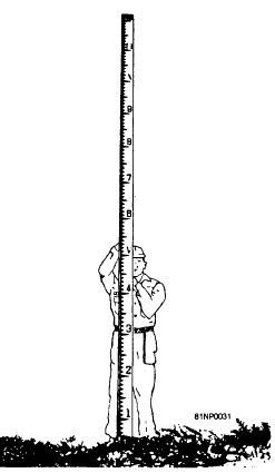
Figure 11-51.-Nadia board.
in figure 11-51. Note that it is graduated in a manner
that facilitates counting the number of graduations intercepted between the hairs. Each tenth of a foot is marked by the point
of one of the black, saw-toothed graduations. The interval between the point of a black tooth and the next adjacent white
gullet between two black teeth represents 0.05 ft.
Other types of graduations on stadia rods or boards are shown in figure 11-52.
Turning-Point Pins and Plates
The point on which a leveling rod is held between a foresight and the next backsight while the instrument is being moved to the next setup
is called a TURNING POINT. It must be sufficiently stable to maintain the accuracy of the level line. Where either proper
natural features of man-made construction is not available, a turning-point pin, a turning-point plate, or a wooden stake
is used. These not only furnish the solid footings but also identify the same position for both sightings. Normally, the pins
or plates are used for short periods and are taken up for future use as soon as the instrument readings are completed. Wooden
stakes are used for longer periods except when wood is scarce or local regulations
require their removal.
A turning-point pin is shown in figure 11-53, view
A. It is made of a tapered steel spike with a round top with a chain or a ring through the shaft for ease in pulling. The
pin is driven into the ground with a sledgehammer. After a turning pin has served its purpose atone point, it is pulled and
carried to the next turning point. Turning-point plates (fig. 11-53, view B) are triangular metal plates with turned-down
corners or added spikes that form prongs and have a projection or bump in the center to accept the rod. The plates are devised
for use in loose, sandy, or unstable soils. The
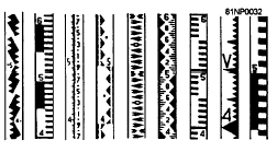
Figure 11-52.-Types of graduations on stadia boards.
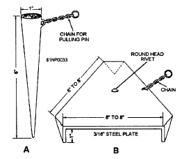
Figure 11-53.-Turning-point pin and plate.
plate is set by placing it on the ground, points down, and stepping on it to press it to a firm bearing. After use, it is lifted, shaken free of dirt
and mud, and carried forward to the next turning point.
Magnifying Glass
A magnifying glass is used mainly to aid the
instrumentman in reading graduations that are provided with verniers, such as the horizontal and vertical circle of a transit.
Although these graduations can be read with the naked eye, the use of a magnifying glass makes the reading easier and decreases
the chance of reading the wrong coincidence.
Two types of magnifying glasses that you will
generally find in the transit box are shown in figure 11-54. They are usually called pocket
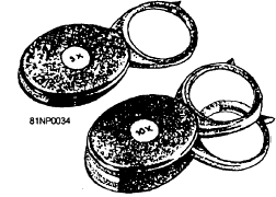
Figure 11-54.-Types of pocket magnifying glasses.
magnifying glasses. To avoid unknowingly
dropping a magnifying glass in the field, you should attach it to a loop of string. The instrumentman puts his head through
the loop, retaining the string around the neck, and carrying the magnifying glass in a pocket. At the end of each day’s
work, it is a good practice always to return the magnifying glass to its proper place in the instrument case.
Adjusting Pins
Surveying instruments are built in such a way
that minor adjustments can be performed in the field without much loss of time while the work is in progress. The adjustments
are made by loosening or tightening the capstan screws that are turned by the use of adjusting pins. These pins are also included
in the instrument box. They come in various sizes that depend upon the type of instrument and the hole sizes of its capstan
screws. Use the pin that fits the hole in the capstan head. If the pin is too small, the head of the screw will
be ruined.
Replacements for these pins are generally given
free of charge by surveying instrument dealers. Like the magnifying glass, adjusting pins should be carried in the pocket
and not left in the instrument box while a survey is in progress. This will save a lot of valuable time when the pins are
needed. Do not use wires, nails, screwdrivers, and the like, as substitutes for adjusting pins.
Tape Repair Kit
Even though you handle the tape properly and
carefully during field measurements, some tapes still break under unforeseen circumstances. During chaining operations, when
the area is quite far from the base of operations, the surveyor should always be sure to have a tape repair kit (fig. 11-55)
with him so that he can rejoin any broken tape in the field, or if the surveyor has brought an extra tape, he can take the
broken tape back to the office to be repaired.
The tape repair kit usually contains a pair of
small snips, the tape sections of proper size and graduations, a hand punch or bench punch with block, an assortment of small
rivets, a pair of tweezers, a small hammer, and a small file. Before reusing a repaired tape, always compare it with an Invar
or Lovar tape to check it for accuracy.
FIELD SUPPLIES
Field supplies consist principally of a variety
of materials used to mark the locations of points in the field. For example, pencils, field notebooks, and spare handles for
sledgehammers
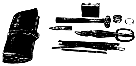
Figure 11-55.-Tape repair kit.
are generally classified as field supplies. Because
SEABEEs operate in so many different places and under such varied conditions, we have not tried to list in this training manual
the supply requirements for every location. From your own experience and with the aid of your leading petty officer, you can
easily make a list of supplies necessary for a projected survey mission. Those items generally required for a mission are
described in this section.
SURVEY POINT MARKERS
The material used as a SURVEY POINT MARKER depends upon where the point is located and whether the marker is to be of a temporary, semipermanent, or permanent
character. For example, a wooden stake can be easily driven to mark the location of a point in a grassy field, but it cannot
be used to mark a point on the surface of a concrete highway. Similarly, though a wooden stake may be easily driven in a grassy
field to mark a property line corner, a marker of this kind would not last as long as a piece of pipe or a concrete monument.
Most of the material commonly used as semipermanent or permanent markers of points in the field is described in the following
sections. For purely temporary marking, it is often unnecessary to expend any marking materials. For example, a point in ordinary
soil is often temporarily marked by a hole made with the point of a plumb bob, a chaining pin, or some other pointed device.
In rough chaining of distances, even the mere imprint of a heel in the ground may suffice. A point on a concrete surface may
be temporarily marked by an X drawn with keel (lumber crayon), a pencil, or some similar marking device. A large nail serves
well as a temporary point in relatively stable ground or compacted materials.
Semipermanent Markers
Wooden hubs and stakes are extensively used as semipermanent markers
of points in the field. The principal distinction between the two is the fact that a hub is usually driven to bring its top
flush with, or almost flush with, the ground surface. A hub is used principally to mark the station point for an instrument
setup. It is usually made of 2- by 2-in. stock and is from 5 to 12 in. long. The average length is about 8 in. Shorter lengths
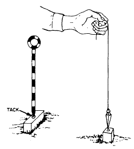
are used in hard ground, longer lengths in softer ground. A surveyor’s tack, made of galvanized iron or stainless steel
with a depression in the center of the head, is driven into the top of the hub to locate the exact point where the instrument is to be plumbed.
Stakes improvised in the field may be either
cylindrical or any other shape available. However, manufactured stakes are rectangular in cross section because the faces
of a stake are often inscribed with data relevant to the point that the stake is marking. A stake that marks a bench mark,
for instance, is inscribed with the symbol that identifies the bench mark and with the elevation. A stake that marks a station
on a traverse is inscribed with the symbol of the particular station, such as 2 + 45.06. A grade stake is inscribed with the
number of vertical feet of cut (material to be excavated) or of fill (material to be filled in) required to bring the elevation
of the surface to the specified grade elevation. Figure 11-56 shows typical dimensions for an average-sized hub and stake.
These dimensions, however, may be modified as situations arise, such as material limitations.
Permanent Markers
Permanent station markers are used to mark
points that are to be used for a long period of time. Horizontal and vertical control stations are
Figure 11-56.-Hub and stakes.
generally marked with permanent markers. These
markers could be in the following forms:
. A bronze disk set in concrete
. An iron pipe filled with concrete
. A crosscut on an existing concrete structure
or on a rock outcrop
. A hole drilled in concrete and filled with
lead or a metal rod driven into the ground with a center-punched mark to designate the exact point
All permanent survey station markers should
be referenced so they can be replaced if disturbed. Methods of referencing points are discussed later in
this training manual.
Surveyor’s tacks, spikes, and nails are often
driven into growing trees, bituminous, or other semisolid surfaces as permanent markers. A nail will be more conspicuous if
it is driven through a bottle cap, a washer, a plastic tape, or a "shiner." A shiner is a thin metal disk much like the top
or bottom of a frozen fruit juice can. A SPAD is a nail equipped with a hook for suspending a plumb bob. It is driven into
an overhead surface, such as the top of a tunnel. The plumb bob will locate on the floor the point vertically below the point
where the spad is driven. Points on concrete or stone surfaces are often marked with an X cut with a hammer and chisel. Another
way to do this is to cut holes with a star drill and then plug them with lead.
A much more durable form of marker is made
of a length of metal pipe—usually called iron pipe regardless of the actual metal used. Lengths run from about 18 to
24 in. Sawed-off lengths of pipe have open ends; pipes cut with a shear have pinched ends and are called pinch pipe. There
are also manufactured pipe markers, some of which are T-shaped rather than cylindrical in cross section. A commercial marker
may consist of a copper-plated steel rod. All commercial markers have caps or heads that permit center punching for precise
point location and stamping of the identifying information.
A still more durable form of marker is the
concrete monument. A short length of brass rod is often set in the concrete to mark the exact location of the point. Concrete
monuments that are used as permanent markers by various federal survey agencies have identifying disks set in concrete, like
those shown in figure 11-57.
Figure 11-57.-Various types of federal marking disks.
Points on concrete or masonry surfaces may
be permanently marked by setting lengths of cylindrical brass stock into holes plugged with lead or grout. Brass stock markers
set in pavement are commonly called coppers. Manufactured brass disks, similar to the ones shown in figure 11-57, may be set
in grouted holes in street pavements, sidewalks, steps, or the tops of retaining walls. Points on bituminous surfaces maybe
marked by driving in pipe, railroad spikes, or case-hardened masonry nails, commonly called PK nails. A center punch for marking
a precise location on metal stock or metal caps is a common item of equipment for a surveyor.
MARKING MATERIALS
KEEL, or LUMBER CRAYON, is a thick crayon used for marking stakes or
other surfaces. Common marking devices that contain a quick-drying fluid and a felt tip are also popular for marking stakes.
All of these types of graphic marking materials come in various colors.
In addition to keel, paint is used to mark pavement surfaces. Paint may be brushed
on or sprayed from a spray can. To make the location of a point conspicuous, use a circle, a cross, or a triangle. Identification
symbols, such as station or traverse numbers, may also be painted on. For a neater job, stencils are sometimes used.
FLAGGING
Colored cloth bunting or plastic tape is often used to make stakes conspicuous so
they will be easier to find or to warn Equipment Operators away. Flagging may also be used for identification purposes. For
example, traverse stakes may be marked with one color, grade stakes with another. Red, yellow, orange, and white are the most
popular colors of flagging.
NOTE-KEEPING MATERIALS
Field notes are usually kept in a bound, standard field notebook. Sometimes loose-leaf
notebooks are used but are not generally recom-mended because of the chance of losing some pages. Notebooks are classified
as ENGINEER’S or TRANSIT FIELD BOOKS, LEVEL BOOKS, CROSS SECTION BOOKS, and so forth, depending on their use. In a transit
book, the left-hand side of the page is used for recording measurement data, and the right-hand side of the page, for remarks,
sketches, and other supplementary information. The other field books generally follow the same pattern of usage. Different
types of field books and inside pages are shown in figure 11-58. Note how each type is lined or gridded. Actually, a transit
or a level book may be used for recording any type of survey. You may add or modify the column headings to suit the required
data you desire to record.
PERSONAL PROTECTIVE AND SAFETY EQUIPMENT
In addition to the necessary field supplies and equipment, a field party must carry
all necessary items of personal protective equipment, such as containers for drinking water, first-aid kits, gloves, and foul
weather gear, as needed. A field survey party is usually working a considerable distance away from the main operational base.
If, for example, you happen to be chaining through a marsh filled with icy water, you would not have a chance to return to
the base to get your rubber boots. You are required to wear a hard hat whenever you work in a construction area where the
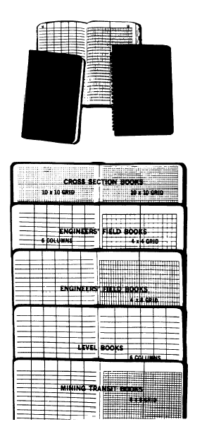
Figure 11-58.-Diffferent types of field books.
assigned personnel are regularly required to wear
hard hats. Do NOT get caught-flat-footed in any situation. To avoid this, you should study the situation in advance—considering
both the physical and environmental conditions.
|